Speaker No. 1786 --- Large DIY 15" 2-way Monitor using SB Audience Products

The speaker plans for this product can be found HERE.
Recently I've been wanting to design a basic 2-way speaker using a 15" woofer for use in home audio. To summarize the design goals:
- High Sensitivity (95dB@1w)
- Compact physical size
- Aesthetically pleasing
- Off the shelf components that are easily available
- High output SPL and low distortion
- Suitable for audiophile two channel or high end home theater as L/C/R duty
- Crossover optimized to audiophile listening and flat frequency response
- Clean, tight bass that is free from 'boxiness' or 'boominess'
- Easy to construct
Enclosure
I'll begin by referring to a quote in Philip Newell's book "Loudspeakers: For Music Recording and Reproduction"
"Nevertheless, the time responses (transient responses) of well-designed sealed boxes with correctly matched drivers and adequate damping can be very accurate. Largely for this reason, sealed boxes have a strong following, and large sealed boxes can be the bases of excellent loudspeaker systems.
A sealed box system is said to be critically damped when its size and the driver resonant frequency are matched such that the overall response is already 6 dB down at the resonant frequency. With this alignment, the transient response can be exemplary, with no perceptible ringing."
The challenge to designing a excellent sealed bass cabinet relies on selecting the correct woofer for the task. If the driver's motor is too weak (High QTS) then distortion increases which is explained by Newell below:
"Some manufacturers have tried to sacrifice system sensitivity by lowering the magnet flux in order to lower the system Q. There is a strong ‘amplifier power in cheap’ lobby, who believe that lower efficiency systems can exhibit higher Qs, and hence can be extended in their low frequency range. What they often seem to fail to realise is that a heavier current in the voice coil and a lower power magnet will drastically alter the ratio of the fixed magnetic field to the variable magnet field. The much higher variable field due to the voice coil current can severely distort the position of the flux lines of the weak, permanent magnet, and give rise to loss of low level detail in the sound and increased levels of intermodulation distortion. This highlights perhaps one of the worse aspects of the use of programmable calculators or computers in the wrong hands – they can lead to good results on paper, but they can give rise to unpleasant side-effects in practice."
A while back I tested the SB Audience Bianco 15" 15OB350 woofer and I really enjoyed the natural and transparent sound offered by this woofer. It occurred to me that perhaps this woofer could be used in a sealed enclosure since it had a unique set of parameters not often found in woofers today. Despite the woofer being specifically designed for open baffle, perhaps it could do well in a sealed enclosure.
To quote Newell's book below...
"The sealed box
The practical realisation of an infinite baffle (the sealed box) is rarely large enough to avoid significantly loading the rear of the loudspeaker, so is best called what it really is, a sealed box. Just as open baffles tend to sound ‘open’, sealed boxes often tend to sound ‘boxy’. However, this need not be the case if the box and driver are of adequate size, well-matched, and if sufficient attention is paid to the suppression of resonances within the box."
--
I first read this chapter about seven years ago and attempted a sealed design using a B&C 15CL76 woofer. That project ultimately failed due to poor sound quality performance. Reflecting back it is now obvious why. The 15CL76 has a very low QTS of 0.33 along with a very high FS of 42Hz. As it turned out, the measured FS of my specific drivers were around 62Hz. They produced virtually no bass as a result. The sound was very boxy as well because of the parallel cabinet walls. This failed project is shown below using the 15CL76. I sold the woofers at a loss and replaced them with some 12” JBL’s and ported the enclosure (bass reflex).

Generally, nearly all modern commercially available woofers have been optimized for reflex alignment with a QTS in the region of 0.3 to 0.38. This makes it very difficult to find a suitable driver that has the balance of parameters needed for a successful sealed design.
However, the SB Audience Bianco 15OB350 has a QTS of 0.57 and an FS of 34Hz. It's these small differences that distinguish between a successful project and a failure.
Some may be pushed away from the idea if we attempt to use software to calculate the optimal cabinet. We get discouraging results if we use WinISD to simulate a solution for the SB Audience Bianco-15OB350 15" woofer.

WinISD automatically calculates a 412 liter enclosure for a QTC of 0.705 (optimally flat). This is far too large to be practically reasonable. If we look at reducing the enclosure volume to something more reasonable, for example 76 liters, then we get the following simulation results.

The QTC raises to 1.061 and results in less bass extension (52Hz vs 43Hz F3).
Is this still okay?
I decided to build a test enclosure to verify the simulation results. I conducted acoustical measurements outdoors using the sealed 76 liter enclosure.
The CAD model of the test cabinet is shown below. I went with a triangle test cabinet to eliminate internal standing wave reflections and to allow corner placement.

The resulting frequency response for the SB Audience Bianco-15OB350 15" woofer is shown below. Despite this woofer being designed for open baffle applications, the woofer actually behaves quite nice in a sealed box.

We get 95dB sensitivity and and F3 of 62Hz. Below this frequency, bass falls at a 12dB per octave slope, which is expected for this type of enclosure.
If we look at the measured impedance curve we have the driver resonant frequency at 66Hz and an easy impedance of 8.8ohm at 150Hz.

These measurements were conducted outdoors. In a domestic listening room we have room boundary reinforcement to help extend the bass response. To demonstrate this I set up the cabinet in my studio. The diagram below shows the location of the speaker against the rear and side wall, along with the mic positioned at the listening position. This would represent a typical setup.

I measured the in-room frequency response which is shown below. Because of the normal room reflections introducing peaks and dips in the response, I applied 1/1 smoothing so that you can understand the general trend.

As you can see, we get bass extension down to 42Hz (F3). Sealed enclosures sacrifice low bass output for transient response, but did we achieve that? As you can see below, we have a very fast step response of only 1.7ms.

How does this compare, for example, against a regular ported 6.5" 2-way monitor? Below is the step response of the Signet SL16 in the same test setup in my studio.

The decay trail is 7.4ms versus 1.7ms with the 15" sealed woofer.

What about distortion? It is obvious that distortion will be higher with the smaller speaker, however by how much? Below is the intermodulation distortion for the Signet SL16 Speaker set to 90dB at 1 meter. IMD is around -43dB at 100Hz (0.70%). This is about the same distortion performance as the 8" SB Acoustics woofer I tested a while ago.

Below is the IMD for the SB Audience Bianco-15OB350 76 Liter Sealed In-Room 90dB SPL 1m. IMD is -61dB at 100Hz (0.09%). The distortion is -18dB lower than the 6.5" 2-way monitor for the same output SPL.

For those using this in a home theater application or for those that are using DSP capability on the bass, there is the option of applying some mild EQ boost to further extend the bass response. However, does applying EQ introduce unacceptable levels of distortion? I attempted to apply some EQ to extend the bass response from 42Hz to 32Hz. I then re-measured to see how much the distortion increased by.
Moving the microphone about 15cm from the driver and measuring the raw frequency response is shown below.

I added a +6dB PEW centered around 32Hz (Q1) as shown in the Hypex filter screen below.

Below is an overlay showing the effect of the EQ on the measured response.

Measuring IMD again at 90dB is shown below. The woofer remains linear despite the addition of +6dB of EQ. In fact, we see no increase in distortion. 
In terms of maximum power handling the woofer is rated at 350w AES and 700w max. Full xmax of 11mm is achieved with 450w of input. Cone excursion as a function of frequency and input power is shown below.

This results in an output SPL of around 121dB at 1m making them very suitable for home theater applications. A trio of cabinets would provide an output of 127dB. How does this compare to a trio of high quality 8" woofers in the same application? If we simulate the xmax limited power handling of the same SB Acoustics 8" mentioned early, each woofer is capable of reproducing 101dB SPL in the bass region. A trio of woofers would total 107dB output capability with distortion in the double digit region. So, the 15" solution has effectively 18-20dB more headroom against a comparable 8" woofer both in terms of actual measured intermodulation distortion and simulated xmax limited output capability. The advantages are not just enjoyed at higher SPL levels, but it's clear these benefits are tangible at normal listening levels. It's my opinion that the lower distortion translates into improved perception of dynamics and what some enthusiasts refer to as 'PRAT' (Pace, Rhythm, And Timing).
High Frequency Section
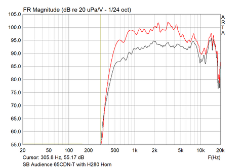
For the high frequency section I used the SB Audience 65CDN-T compression driver with the SB Audience H280 horn lens. I chose this compression driver because it covers a wide frequency spectrum with strong authoritative output even down to 600Hz. The upper treble is very transparent and smooth, and free from any objectionable sound character.
The raw frequency response of this driver/horn combination is shown below red. The grey response is shown with my passive crossover which contours the mid-band down. I also had to modify the compression driver to flatten the response. Details on the modification is shown in the plan set and is simple to do but requires some hardware from your hardware store.
Completing the low pass section is shown below. I used a 3rd order electrical slope for both the bass and treble portions.

Combining the response is shown below. This includes the modification to the compression driver.

Please note that the actual speaker sensitivity is 95dB despite the above graph showing 90dB.
Burst decay is shown below. The peak at 17kHz is a resonance about -25dB down. For me personally, I can only hear to about 14kHz with my 42 year old ears. So if you can hear above these frequencies then perhaps a super tweeter might be advantageous.

Limiting the burst decay results to under 10kHz is shown below. This allows better visualization of the results up to 10kHz.

CSD is shown below and we certainly do see the high Q resonance which appears to be centered around 19kHz. Below this ferquency the CSD shows very fast decay time on par with the best high frequency drivers available.


Distortion (Complete Speaker)
Intermodulation distortion for the complete speaker is shown below.
Using a test signal of 90dB SPL, The woofer starts out with -60dB distortion in the 100Hz region rising to -50dB near the crossover point at 500Hz. Once the compression driver takes over distortion is back down to -70dB, an astonishingly low number for a speaker.

Intermodulation distortion for high frequencies at 90dB is shown below. Distortion remains low at -65 dB rising at 5kHz to around -60dB at 10kHz. Since the distortion is so low, it is advisable to use only very high quality amplification. The amplifier could easily become the bottleneck to low distortion playback. Pay close attention to the nonlinear characteristics of your chosen amplifier especially when the amplifier is operating at an output level below 1 watt. For information on this topic I suggest you read some reviews at Audio Science Review. At 90dB we are talking only 200 milliwatts of output power. Most amplifiers are into their noise floor at this output level. For example the Parasound 2125 V.2 Amplifier Review shows harmonic distortion at -70dB (1kHz) for 200mw of output.

Anyways, back to the results. The intermodulation distortion is shown below.

Harmonic Distortion for 90dB is shown below.

Speaker Plans
I am offering the plan set for this project for the DIY enthusiast. There are multiple configurations depending on your skill level. The HF horn can be mounted into the enclosure, or the horn can be positioned on top of the cabinet. There are two variations for top mounting the horn. The first is a basic support frame. The second is a more elaborate frame. Chose the design that fits with your visual preference and capability.
The version with the horn mounted into the enclosure is shown below.


The second configuration (shown below) is with the horn mounted on top of the enclosure. This method eliminates the need for the support stand and positions the listening height at 90cm. It also allows for the compression driver modification I mentioned earlier.


The third configuration is shown below. This adds thick solid hardwood bezel to the horn similar to a picture frame. This is just an esthetic choice and has no affect on sound quality. The picture frame is a little more difficult to construct but may be preferred visually to some people.


The plans include assembly and detail drawings to construct each version, along with the passive crossover schematic to construct the crossover.
I chose a corner cabinet design so that the speaker could be placed well into the corner of the listening room. This maximizes bass response however it is not necessary. I found great bass response even with the speakers placed 70cm from the side walls and 15cm from the rear wall. If using the speaker in the corner of the room, the speaker only protrudes from the corner by 40cm (15.75")

The render shown below highlights how discreet the speaker can be in a normal living room.

For aesthetic purposes the woofer is rear mounted into the enclosure. This requires that the side panel be removable on the cabinet. This is optional of course. The driver can be front mounted if you'd like and simplifies cabinet construction even further, but means an exposed driver frame and doesn't look as clean as the rear mounted configuration.

The instruction package includes both assembly drawings (shown above) and detail drawing (shown below) for each component of the assembly. The assembly drawings only show the arrangement of the components. The dimensions for construction of each component is shown on the detail drawings.

The Bill Of Material (BOM) is located on the assembly drawings. It highlights the list of detail drawings associated with the cabinet. For example, cabinet 1786-04 is made up of seven components or parts numbers as shown below.

The specific detail drawing number in shown in the drawing title block shown below.

Cabinet Material
The cabinet material is standard 18mm thick birch plywood. You can also use marine ply or apple ply as well. If you decide to use MDF, please double the wall thickness or use use substantial internal bracing and account for the bracing for the internal volume. It is recommended to avoid MDF if at all possible for this reason.
Cabinet Stuffing
The cabinet is to to be stuffed 100% full of polyfill (pillow stuffing). The pillow stuffing should not be compressed in any way. It must be loosely filled in the enclosure enough to fill all the voids.
Support Stand
A basic drawing is provided for the support stand, which can be either wood or metal depending on your preference. The stand is only required if you want the speaker positioned at the proper listening height when the horn is mounted in the enclosure (configuration 1).

Crossover
The crossover schematic includes suggested part numbers which have been optimized for the best sound quality. The final tuning of the crossover was based on extensive music listening to a variety of tracks. Acoustical measurement was used to verify a flat frequency response, but it was not the end goal, even though the response is very flat, the end goal is excellent subjective sound quality.
