Autoformer Versus Fixed Resistor L-Pad --- IMD comparison

I've been getting a lot of questions regarding autoformers and whether they are beneficial in terms of sound quality. Normally I use autoformers to provide some MF and HF adjustment based on the customer's request. However recently I've been getting inquiries as to thier sonic virtue compared to a fixed resistor L-pad.
For context, I design custom horn speakers for home use which often requires significant attenuation of the mid and high frequency compression drivers.
I was able to have Dave at Intact Audio send me a pair of his Loudspeaker Level Autoformers to evaluation. I asked Dave what test method would bring to light the benefits of the autoformer. Dave was short on answers but did like my suggestion to use multitone intermodulation distortion as metric for evaluation. So here we go!

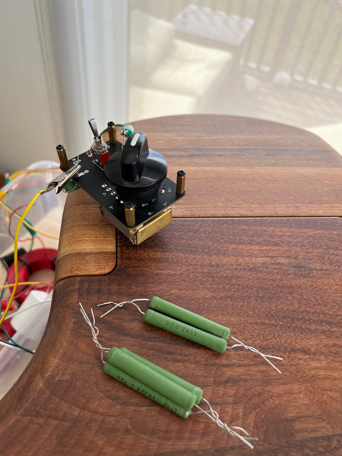
So I decided to compare his Autoformer against the same attenuation circuit comprised of a fixed resistor L-Pad as shown below. The circuit provides -17dB of attenuation.

The net value for R1 and R2 are 7.3ohm and 1.1ohm. I've ganged the resistors to dissipate the required power. Each resistor has a thermal capacity of 10w, however I typically over-specify these values in my circuits to account for transient power spikes with regular music (look up Crest Factor for more info). Side note, for a handy series parallel resistor value calculator, look at Digikey's online calculator here.
For the comparison test I simply replaced the resistors with the autoformer which was set to -17dB on the dial. The Intact Autoformer has a labelled circuit board providing indication of the desired attenuation. The knob has a nice detent action to each value, making easy repeatability.
I decided to include both solid state and tube amplification in this test. This will potentially capture any benefit the autoformer may have depending on amplifier type.
For the test, I decided to fix the output voltage from the amplifier to 1V which provided 85dB at 1m from the horn, using -17dB attenuation. The horn and driver used in the test is the BMS 4591 with horn No.1670 which is my own ES290 Biradial.

The mic used is the ACO Pacific 7042 condenser mic feeding into the Focusrite Scarllet Solo preamp which is then fed to my laptop running ARTA measurement software. On the output side I am using the Topping D10S USB DAC feeding an analogue signal to the respective amplifier.
The amplifiers used in the test are relatively low power, with both having a maximum output power of only 18w at 8ohm. The amplifiers are described below.

Tube Amplifier
Meixing Mingda MC368-B902 KT90 Single Ended Triode
Solid State Amplifier
Custom built unit using HifiSonix SX Amplifier Circuit Board designed by Andrew C. Russel, Pure Class A, 18w
Third last minute contender (Class D)
Hypex FA501 500w Class D plate amplifier with DSP
For a test signal I'm using ARTA's 12 band/octave multitone test signal ranging from 300Hz-8kHz set to 1.00v at the amplifier output which amounts to 85dB output SPL at 1m from the mouth of the horn.
Test Results
Below is the IMD result for the tube amplifier using fixed resistors. Click on the image to enlarge. A text description is shown at the bottom of the graph for reference. For this result we see -55dB at 1kHz (0.17%).
Side Note: IMD is measured as the difference between the peaks of the test signal and the dark grass area near the bottom of the chart. Counting vertically using the left side scale reveals the IMD amount. For example, we see that at 300Hz, the test signal is -59dB while the dark grass area is at -110dB, the difference being 51dB IMD. A greater difference equates to better performance. I use IMD as a test metric because it correlates better to perceived sound quality compared to harmonic distortion.

If we switch to the autoformer we get the following result. We see IMD increases by +2dB. IMD is now at -53dB. We are seeing IMD get worse with the autoformer.

Switching over to the solid state amplifier using the fixed resistor L-pad we get the following result. IMD is -70dB for the 1kHz region.

Switching to the autoformer we get the following result. We see no change in IMD between the fixed resistors and the autoformer.

Additional Testing
I noticed during my testing that the tube amplifier produced much lower distortion if the output voltage was reduced and the attenuation reduced to only -1dB. Below is the IMD result for the same output SPL as above, but with the autofomer set to -1dB (insead of -17dB) and the amplifier's volume control reduced by 16dB. This resulted in an output voltage of 0.17v. I should note as well, both 1v and 0.17v are well below 1w output from the amplifier! IMD improves to -62dB at 1kHz.

The implications of this, at least for tube amplifers, so far, is that the lowest distortion solution is no speaker level attenuation at all. It is much better to attenuate the line level signal instead.
I then decided to conduct the same test with the pure class A solid state amplifier. Below is the result for that test. We can see that IMD is -70dB at 1kHz. So again, the lowest distortion solution is to bypass the speaker level attenuation entirely, when using this type of amplifier (18w solid state class A).

Taking it a step further, I decided to test the Hypex FA501 Class D amplifier. We can see that we take a massive hit with IMD at -54dB. I should note that the test signal in ARTA had to be reduced by 15dB to account for the higher gain provided by the 500w amplifier versus the 18w for the other two amplifiers.

But how does the Hypex compare if we reintroduce the -17dB attenuation using the autoformer? We see IMD improve to -71dB at 1kHz, however we unexpectedly see distortion rise in the 4kHz region to -61dB. This does not compare favorably to the Class A amplifier where we see IMD at -64dB in this region. So perhaps the Hypex needs further attenuation?

Conclusion
We see that the autoformer offers no improvement in sound quality when looking at intermodulation distortion, compared to a fixed resistor solution. We even see a slight increase in IMD with the autoformer and tube amplifier combination.
Through additional testing, I found that greater sound quality improvements can be had when eliminating any kind of speaker level attenuation, if the amplifier is of reasonably low gain (output power).
The Hypex FA501 did not compare favourably due to improppper gain structure. Using only a fraction of a watt from a 500w amplifier put us into the noise floor, even after attenuating the output by -17dB, we still saw inferior performance to the solid state class A solution.
When dealing with high sensitivity drivers such as the BMS 4591 at 118dB, care must be taken to ensure gain structure is even and balanced so as to keep each device in its optimal operating range. I found that even the tube amp performed better when operating at 0.13v (2 milli-watts Mw) output versus 1v (1/8 watt).
This highlights why perhaps flea power tube amplifiers have such a strong following!
Do L-Pads Add Distortion?
Does a fixed resistor L-pad add distortion? I found that in the case with low power tube amplifiers, the addition of the L-pad had a detrimental effect. This was due to the imbalance in the gain structure by the addition of the L-pad.
We also found that the addition of the L-pad helped lower distortion when using a high a high power amplifier (Hypex FA501 500w). The L-pad helped balance the gain structure between the amplifier and loudspeaker, thereby lowering amplifier distortion.
So in the end, an L-pad or Autoformer is a tool to balance gain structure for optimal sound quality. It does not appear to inherently introduce distortion on it's own.