


In this blog post I look at adding a waveguide to the Dayton Audio AMTPRO-4 tweeter.

I had a local company 3D print two different waveguide designs so that I could compare the following:
Test Configurations
- Open air with mounting bezel removed
- Mounted to baffle 25cm wide
- ES Waveguide (No Fins) No.1905-01-001
- ES Waveguide (With Fins) No.1905-01-002
Below shows the mounting bezel removed tested open air.

Below shows the tweeter mounted in a baffle 25cm wide.

Below shows ES Waveguide No.1905-01-001.(No fins)


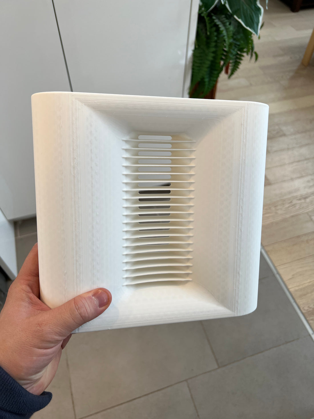
Below shows the same waveguide however with fins (No.1905-01-002)


Open Air Test
I start by measuring the response with the tweeter open air with the mounting bezel removed at 0,15,30, & 45 off-axis (Blue, Green, Red, Purple).

25cm Wide Baffle
I then measured the response mounted to a 25cm wide baffle which is shown below.

ES Waveguide No.1905-01-001 (No fins)


I then mounted the AMT tweeter to the waveguide with no fins. The resulting frequency response is shown below.

ES Waveguide No.1905-01-002 (With fins)
Below is the response of ES waveguide 1905-01-002.

If we take the best two responses which was open air and the waveguide with fins and overlay them, we can see how they compare. (Red open air, green waveguide with fins)

If we take the same comparison and look at the response 30 degrees off-axis we get the following result. (Red open air, green waveguide with fins)

Conclusions
The open air solution offers a well behave off axis relative to the on-axis. The response in the region from 1kHz-5kHz is relatively flat and does not have the rising response that we see when mounted in a baffle. The peak at 11kHz seems pronounced.
Dayton Audio AMTPRO-4 Open Air shown below.

The 250cm wide baffle presents some challenges. As you can see below, the on-axis response would require some work if doing a passive crossover. A contour circuit may be required to compensate for the rising response from 1kHz-5kHz. The peak at 11kHz is tricky. If you notch it out with a filter then it would introduce a dip when measuring 30 degrees off-axis.
25cm Baffle On-Axis shown below.

The waveguide with no fins is shown below. We see sensitivity increase of +2.5dB at 1.5kHz compared to the open air and baffle mount configuration.

The finned version provides the most linear response. (see below) The fins seem to help reduce the peak at 11kHz and smooths out the response across it's bandwidth. There is still the pesky dip at 4.6kHz. I'm not sure where this is coming from.
 Distortion
I only had opportunity to measure distortion on waveguide 1905-01-002 (no fins). It took some effort to get my room quiet enough to fully reveal the noise floor of the driver. I had to add a 22ohm resistor in series with the tweeter to eliminated hiss from the amplifier (Hypex FA501). Below is the environmental noise of the test space for reference.

Below is the 12 band per octave test signal playing test tones from 1kHz - 20kHz. With a test SPL of 85dB at one meter we can see that distortion artifacts are -82dB in the lower midrange jumping to -68dB at 3kHz which is still within my target for audiophile sound quality. Distortion then improves to -75dB in the 7kHz region which is an excellent result.

Increasing the test SPL to 95dB is shown below. 
Subjective Listening
The AMTPRO-4 came with two felt pads that are friction fit over the rear of the driver. I had difficulty doing this test because the felt pads did not fully absorb the rear wave, and so it would introduce comb filtering into my measurements as the rear wave made its way back around to the front. I had to add additional damping material to the rear of the driver (in the form of a dish cloth no less) to block the rear wave so that I could get a clean measurement at the front of the driver.
When I first listened to the driver I was not impressed because it lacked low level detail retrieval. The obvious thing to try was to then remove the rear damping materials and allowed it run open at the rear.
This cleared up the sound quality and the tweeter sounded quite good.
When making listening comparisons, I found the finned waveguide to have a little more clarity than the others.
I tried a variety of crossover points and found that the tweeter did well with a 1.5kHz crossover point using either a 2nd or 4th order slope.
…But wait, there’s more…
I then installed a 3D printed fin set for the rear of the tweeter. My idea here is to help balance out the acoustic loading on the diaphragm between the front and rear of the driver. Why spend all the work on the front only? Once these rear fins were installed I noticed the sound quality jumped another level.

I attempted to measure the effect however the rear wave interfered with my measurements so I was not able to demonstrate the improvements. Subjectively, If I listened to the rear wave coming off the tweeter it sounded 'cupped'. When I installed the rear fins the cupped sound disappeared. I can only guess that this cupped sound is a result of the parallel walls formed by the magnet structure.
I had fun experimenting and the 3D printing allows for rapid prototyping, and more importantly I don’t have to do the printing which leaves me with more time for things like 3D CAD design and testing. From here I have even more ideas on how to improve things further which will have to be for another blog post.